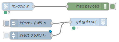
This simple example uses RPi-GPIO nodes to read and write to Opto 22 digital I/O modules.
Note: You can test this flow without using Opto 22’s Digital I/O for Raspberry Pi® Starter Kit (AC/DC) or Digital I/O Carrier Board for Raspberry Pi—but where’s the fun in that?
If you don’t have the RPi-GPIO nodes, you can install them from a terminal emulator with this command:
npm install rpi-gpioIn this flow:
- The rpi-gpio in node reads the value (1 or 0) of pin 40. If the value changes, the msg.payload (debug) node writes a message to the Node-Red Editor’s debug tab.
- For the rpi-gpio out node:
- Every 2 seconds, the inject 1 (Off) node writes a “1”.
- Every 3 seconds, the inject 0 (On) node writes a “0”.
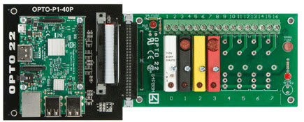
Using this flow with digital I/O modules and Opto 22’s Digital I/O Carrier Board for Raspberry Pi®, the LED status indicator on the module at position 3 flashes off and on, because the two inject nodes are constantly changing its value.
You won’t notice any change to the LED on the module at position 0 because the rpi-gpio in node only reads the value. (It doesn’t write to the module.)
Steps
Important: Opto 22 I/O modules use negative true logic (a zero bit means On and a 1 bit means Off).
When you read and write to I/O points, 0 is On and 1 is Off.
-
If you’re using real I/O with this example, make sure on the rack there’s a digital input module (like the G4IDC5MA) in position 0, and a digital output module (like the G4ODC5) in position 3.
-
Import this flow into the Node-Red Editor:
[{"id":"64d481ac.e098","type":"rpi-gpio in","z":"9c20b8dc.4e6bb8","name":"rpi-gpio in","pin":"40","intype":"tri","debounce":"100","read":false,"x":70,"y":73,"wires":[["37605114.4763a6"]]},{"id":"7f075d13.d50a9c","type":"inject","z":"9c20b8dc.4e6bb8","name":"inject 1 (Off)","topic":"","payload":"1","payloadType":"num","repeat":"2","crontab":"","once":false,"x":121,"y":138,"wires":[["44140ea4.e7c4d"]]},{"id":"44140ea4.e7c4d","type":"rpi-gpio out","z":"9c20b8dc.4e6bb8","name":"rpi-gpio out","pin":"35","set":"","level":"0","out":"out","x":341,"y":133,"wires":[]},{"id":"329323dd.c025c4","type":"inject","z":"9c20b8dc.4e6bb8","name":"inject 1 (On)","topic":"","payload":"0","payloadType":"num","repeat":"3","crontab":"","once":false,"x":120,"y":185,"wires":[["44140ea4.e7c4d"]]},{"id":"37605114.4763a6","type":"debug","z":"9c20b8dc.4e6bb8","name":"","active":true,"console":"false","complete":"false","x":339,"y":73,"wires":[]}] -
Deploy the flow.
- If your Pi is connected to I/O:
- The LED status indicator on the module at position 3 will flash off and on.
- If the module at position 0 has a switch, you can flip it to change its value, and then see the results logged on the Node-RED Editor’s debug tab.
- If you’re not using I/O, you can still read the values produced by the nodes. It just won’t be as much fun.
- If your Pi is connected to I/O: