For a mapping diagram and overlay for your Pi, see Pin-to-Module Mapping.
Each of these code samples uses a different method to read and write to I/O points.
You can use any Pi operating system and programming language to read and write to I/O points.
Just remember:
- Opto 22 I/O modules use negative true logic (a zero bit means On and a 1 bit means Off).
When you read and write to I/O points, 0 is On and 1 is Off. - Before reading or writing to an I/O point, you must configure its associated GPIO pin as an input or output. (Use the Opto 22 Pin-to-Module diagram to see how GPIO pins are mapped to I/O points.)
- If the GPIO pin is mapped to an input module, make sure to configure it as input;
if it’s mapped to an output module, make sure to configure it as output. - Once you configure the GPIO pin, you don’t need to change it (unless you swap out the Pi or connect the same carrier board to a rack with different I/O).
- If the GPIO pin is mapped to an input module, make sure to configure it as input;
- You can both read and write to output points (0 for On; 1 for Off).
- For input points, you perform reads (0 is On; 1 is Off).
If you accidentally write to an input point, no problem—nothing will happen.
Terminal
You can issue read and write commands from a terminal.
The examples in this section show LXTerminal on a Pi running Raspbian.
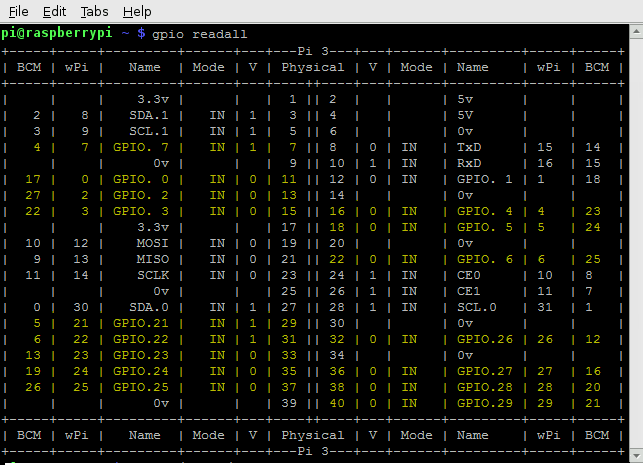
Read all GPIO pins
A value of 0 means the I/O point is On; 1 means it’s Off.
Syntax
gpio readall
In this image, highlighted GPIO pins are mapped to I/O points.
For a mapping diagram and overlay for your Pi, see Pin-to-Module Mapping.
Read a GPIO pin
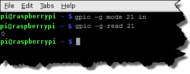
This example:
- Configures GPIO pin 21 as input.
- Reads the input point mapped to GPIO 21 and writes its value to the terminal.
The input point is at rack position 0, and its status is 0 (On).
Syntax
gpio -g mode [GPIO pin number] in
gpio -g read [GPIO pin number]
Write to output
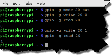
This example:
- Configures GPIO pin 20 as output.
- Turns On the output point mapped to the GPIO.
- Reads and writes the point’s value to the terminal.
- Turns Off the point.
- Reads and writes the point’s value.
Syntax
gpio -g mode [GPIO pin number] out
gpio -g write [GPIO pin number] 0
gpio -g read [GPIO pin number]
gpio -g write [GPIO pin number] 1
gpio -g read [GPIO pin number]
The Pi Filesystem
The Pi filesystem is accessible from any programming language and also from a terminal.
The files that control GPIO pins are located in /sys/class/gpio.
Read a GPIO pin
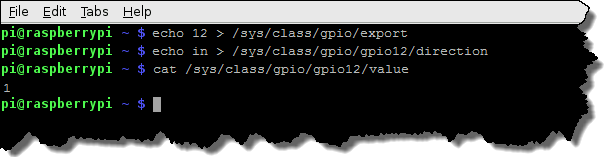
This example:
- Establishes access to GPIO pin 12.
- Configures the GPIO as input.
- Reads the input point mapped to GPIO 12 and writes its value to the terminal.
(The input point is at rack position 7 and its status is 1 (Off).)
Syntax
echo [GPIO pin number] > /sys/class/gpio/export
echo in > /sys/class/gpio/gpio[GPIO pin number]/direction
cat /sys/class/gpio/gpio[GPIO pin number]/value
Write to output
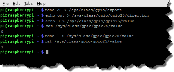
This example:
- Establishes access to GPIO pin 25.
- Configures the GPIO as output.
- Turns On the output point mapped to the GPIO.
- Reads and writes the point’s value to the terminal.
- Turns Off the point.
- Reads and writes the point’s value.
Syntax
echo [pin number] > /sys/class/gpio/export
echo out > /sys/class/gpio/gpio[pin number]/direction
echo 0 > /sys/class/gpio/gpio[pin number]/value
cat /sys/class/gpio/gpio25/value
echo 1 > /sys/class/gpio/gpio[pin number]/value
cat /sys/class/gpio/gpio25/value
RPi.GPIO Python Library
If you code in Python, the RPi.GPIO Python library (included with Raspbian) lets you configure, read, and write to GPIO pins.
sudo apt-get install RPi.GPIOIf the library’s already installed, you’ll get a “…is already the newest version” message.
Otherwise, the package will download and install.
We’ve created a Python script that shows how to read and write with the RPi.GPIO library.
-
If you’re using a browser, click here for the script.
-
To download the script to the current directory using a terminal, enter
wget http://developer.opto22.com/downloads/PythonScript.py
To print the working directory, enter
pwdTo view the script, enter
more PythonScript.py The comments in the script point out where it:
- Invokes the Python interpreter
- Includes the RPi.GPIO library and sets GPIO as a local name in the script
- Sets the pin-numbering scheme for the script
(TheGPIO.BOARDoption means that that you’re referring to the pins by their physical pin number. To refer to the pins by their GPIO pin number, use theGPIO.BCMoption.) - Configures physical pin number 13 as input.
Note: Physical pin 13 is mapped to rack position 10. - Reads the input point mapped to pin 13 and stores it in a variable.
- Prints the point’s value to the terminal.
- Configures physical pin number 15 as output.
Note: Physical pin 15 is mapped to rack position 11. - Turns On the output point mapped to pin 15.
- Turns Off the output point mapped to pin 15.
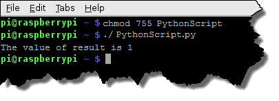
To run the script:
- If necessary, modify the pin numbers in the script to correspond to I/O modules on your rack.
- Make the script executable by entering
chmod 755 PythonScript.py - Run the script by entering
./PythonScript.py
The output looks something like this:
Opto 22’s Configure/Read/Write Script
To simplify accessing I/O when you write your own code, we’ve written a Python script that your code can reference.
-
If you’re using a browser, click here for the script.
-
To download the script to the current directory using a terminal, enter
wget http://developer.opto22.com/downloads/Opto22.PI.py
To print the working directory, enter
pwdTo view the script, enter
more Opto22.PI.py The script references an I/O module’s rack position to read and write to its point, and to configure its associated GPIO pin. It also contains comments to help you understand what it does.
How to run Opto22.PI.py
Open a terminal, and then run the script using this syntax:
sudo python Opto22.PI.py [module number] [command] [value]
- [module number] : Rack position of the target I/O module (0 through 15).
-
[command]
:
- blink makes the GPIO pin blink.
- config configures the I/O module's associated GPIO pin as either input or output.
- read reads the status of the I/O point.
- write turns an output point On or Off.
-
[value]
:
-
If [command] is blink, for [value], type the number of seconds to blink. The minimum value is 2 (blink on for 1 second; blink off for 1 second).
- If [command] is config, [value] is
inputoroutput.
You must configure the GPIO pin to match the I/O module's type.- If the GPIO pin is mapped to an input module, enter
inputfor the value. - If the pin is mapped to an output module, enter
outputfor the value.
- If the GPIO pin is mapped to an input module, enter
-
If [command] is read, you don't need the [value] argument. Leave it blank.
- If [command] is write, [value] is
1for On or0for Off.
Important: The Opto22.PI.pi script is coded to use 1 for On and 0 for Off. -
Examples for LXTerminal
config option to configure the GPIO pin’s direction to match the type (input or output) of its associated the I/O module.Configure the GPIO pin mapped to rack position 0 as input
sudo python Opto22.PI.py 0 config input
Read the I/O module at rack position 3
sudo python Opto22.PI.py 3 read
Turn Off the I/O module at rack position 15
(Remember that in Opto22.PI.py, 1 = On and 0 = Off)
sudo python Opto22.PI.py 15 write 0