Overview
In this second example, we’ll write an incrementing integer value to the Scratch Pad area of the OptoMMP memory map.
The goals of this example are:
- The client will connect and attempt to reconnect if there are any errors.
- The write requests will trigger as often as possible. Once a request’s response has been processed, the next one will be triggered.
This example assumes you have basic familiarity with creating and running an application in the CODESYS Development System. It also assumes you’ve read the Hello, world! example.
Step 1 - Determine the OptoMMP Address to Use
The value will be written to Element 0 of the Scratch Pad 32-bit Integer area.
The OptoMMP memory map address can be determined in two ways.
- In the “Appendix A: SCRATCH PAD—READ/WRITE” section of the OptoMMP Protocol Guide (form 1465).
- With the MMP Calculator tool in groov Manage. From the Home page, click I/O > I/O Services > MMP Calculator.
The OptoMMP memory map address is 0xF0D81000.
Step 2 - Create and Prepare Project
- Create or open an application within the CODESYS Development System.
- Make sure the Opto 22 Library, version 3.0.0.0 or later, is added to the Library Manager.
- Create a new POU named
MMP_WRITE_INTEGERwith Continuous Function Chart (CFC) as the implementation language. - Add the new program to the Task Configuration.
-
Add the following variables to the Declaration area of the
MMP_WRITE_INTEGERprogram.PROGRAM MMP_WRITE_INTEGER VAR mmpClient: OPTO.MmpClient; mmpWriteUDINT: OPTO.MmpClientWriteUDINT; udiVar : UDINT; END_VAR - Drag out a Box onto the CFC editor and assign it the
ADDfunction. -
Configure the inputs and outputs like this:
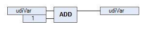
This will add 1 to
udiVarevery time the CFC program is called.
Step 3 - Initialize the MmpClient Instance
Often it’s desirable to keep a client connected as much as possible. This can be accomplished by taking the client’s xError output, negating it, and then feeding it back into the xConnect input.
- In the declaration editor, double-click the
mmpClientvariable and drag it into the implementation area. - Assign
'127.0.0.1'tosAddress. - Connect the
xErroroutput to thexConnectinput. - Deselect the new connecing line.
-
Right-click on the pin for
xErrorand select Negate. This should add a small circle at the beginning of the connecting line leavingxError. Make sure there’s not another circle at the other end of the connecting line.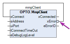
Connecting xError and xConnect in this way will enable the following behavior:
- Initially,
xErrorisFALSE, which causesxConnectto beTRUEand begin the connection process. - While connecting,
xErrorremainsFALSEandxConnectremainsTRUE. - Once connected,
xConnectedbecomesTRUE,xErrorremainsFALSE, andxConnectremainsTRUE. - If there’s an error (either while connecting or once connected),
xErrorbecomesTRUEwhich forcesxConnecttoFALSE.- On the next cycle, the process begins again. Due to the state change on
xConnect,xErroris cleared and goes back toFALSE, sendingxConnecttoTRUEagain.
- On the next cycle, the process begins again. Due to the state change on
It may take one or more PLC cycles for any of the states changes to complete.
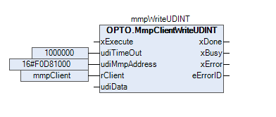
Step 4 - Initialize the MmpClientWriteUDINT Instance
- In the declaration editor, double-click the
mmpWriteUDINTvariable and drag it into the implementation area. - A few of the inputs need to be set.
- Assign
1000000toudiTimeOut. - Assign
16#F0D81000toudiMmpAddress.- This is the OptoMMP memory map address that was determined in Step 1.
- Assign
mmpClienttorClient.- This is a reference to the client.
- Assign
As stated in the Overview for this example, we want to write the udiVar value as often as possible. This can be accomplished by taking the MmpClientWriteUDINT block’s xBusy output, negating it, and then feeding it back into the xExecute input.
- Connect the
xBusyoutput to thexExecuteinput. - Deselect the new connecing line.
-
Right-click on the pin for
xBusyand select Negate. This should add a small circle at the beginning of the connecting line leavingxError. Make sure there’s not another circle at the other end of the connecting line.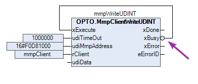
Connecting xBusy and xExecute in this way will keep writing the value as often as possible.
- Initially,
xBusyisFALSE, which causesxExecuteto beTRUEand begin the process. - While executing,
xBusybecomes and staysTRUEandxExecutebecomesFALSE. This does not stop the current request from being processed. - Once the response is done being processed,
xBusybecomesFALSE, causingxExecuteto becomeTRUE, thus starting the next request. - If there’s an error,
xErrorbecomesTRUEandxBusybecomesFALSE, which forcesxExecutetoTRUE, thus starting the next request.- Your real-world application might require more sophisticated error handling.
- A common error would be caused by the MmpClient not being connected, such as when first starting the program or during a networking issue. The request can still run as often as possible, but will quickly report an error and try again. Once the client is connected, the next request should succeed.
- Additional details are in the CODESYS help documentation for Edge Triggered Function Blocks of the Common Behaviour Model.
Finally, we need to feed th udiVar variable into the write block. This can be done by directly assigning udiVar to the udiData input. Or, for a more visual approach, the ADD block can be connected to the write block, like this:
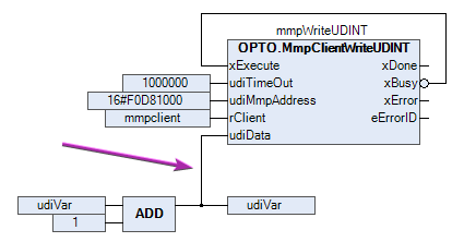
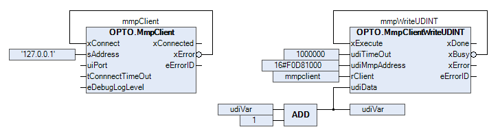
The final program should look like this:
Step 5 - Run and View Results
Before running the application, use groov Manage to view the Scratch Pad value.
- In groov Manage, navigate to Home > I/O > I/O Services > Scratch Pad.
- For Data Type, select 32-bit Integer.
- For Index, enter 0.
- For Length, enter 1 or more.
Back in CODESYS:
- Go into Online mode.
- Run the application.
If all goes well, there should be a solid blue line between the client’s xError output and xConnect input. The write block’s xBusy should be cycling between TRUE and FALSE, as each request is completed.
Back in the Scratch Pad page in groov Manage, the Scratch Pad element should be increasing.
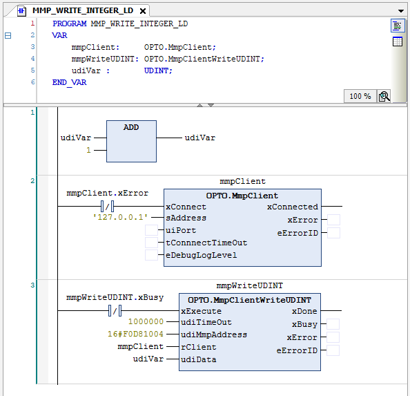
Ladder Logic Version
This example in Ladder Logic (LD) is very similar. Here’s one way it could be written:
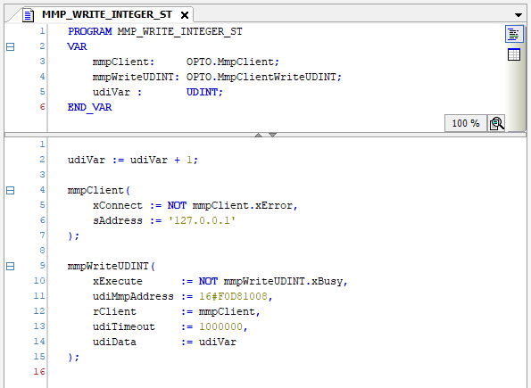
Structured Text Version
This example in Structure Text (ST) is very similar. Here’s one way it could be written:
Next Step
Continue on to the Reading an Integer Array example.